Views and marks
Views, and the markers that link them
The views come from the model. Each has its own settings, and its marker is drawn in the other views, styled from the SECTIONS tab.
The views of a model
The views are the model's section planes (SketchUp), its Occlusia sections (Blender), or the plans and elevations made for an IFC or FBX file. Active Section chooses the one drawn; the SECTIONS tab lists them all.
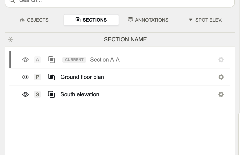
- The letter or number beside a name is the view's symbol, set in the model.
- The current view is marked and cannot be edited or hidden from this list.
- Each view keeps its own visibility choices, shadows and PDF page setup. Views sharing a name share them: give every view its own name.
Section markers
A view's marker — its cut line and the heads at its ends — is drawn in the other views, never in its own: Section A-A's line in the plan, the plan's line in the section.
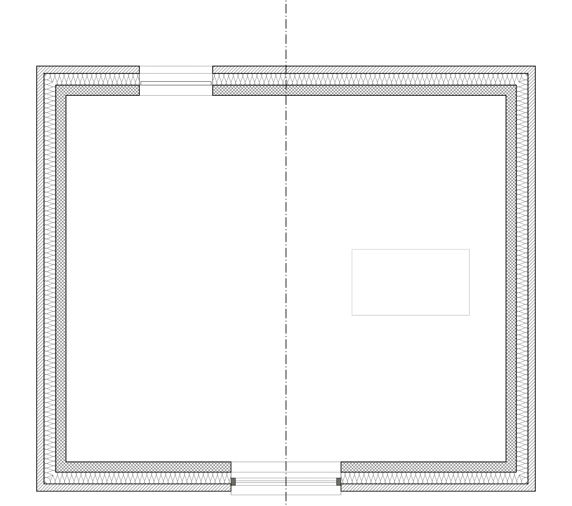
Open a view's gear in the SECTIONS tab to style its marker:
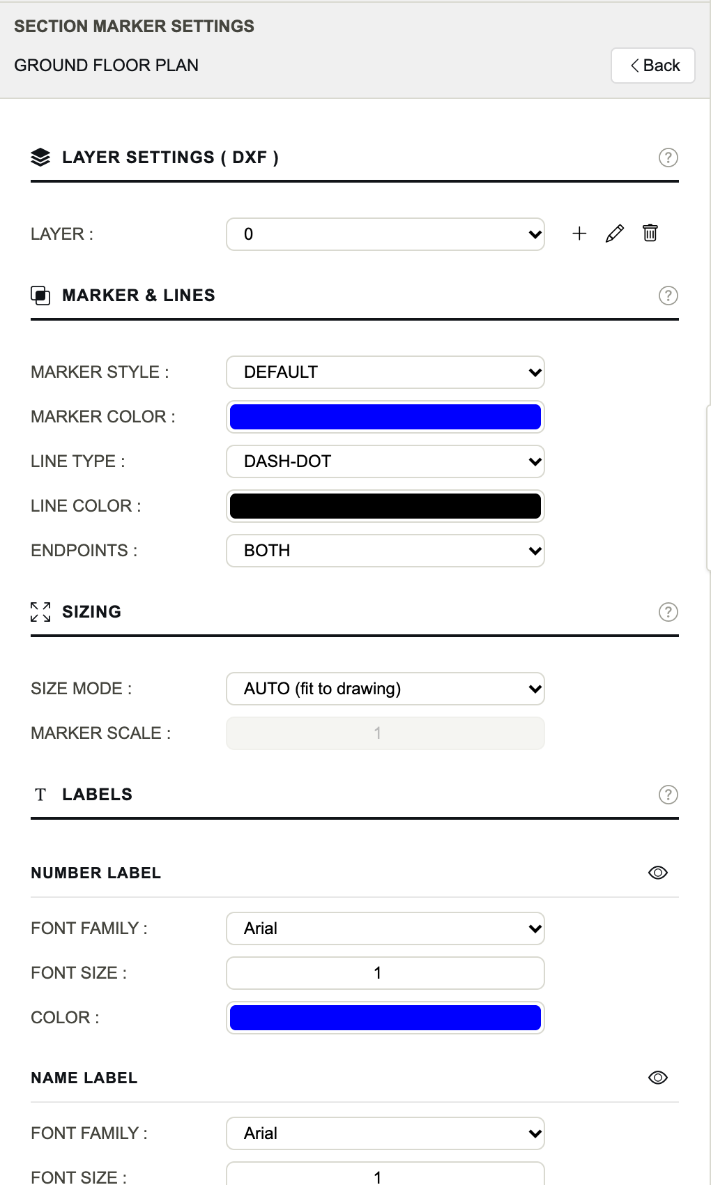
- Layer
- The DXF layer of the marker.
- Marker Style
- DEFAULT (a disc with the symbol and the name), CLOSED ARROW or OPEN ARROW.
- Marker Color
- The colour of the heads. Blue by default.
- Line Type / Line Color
- The cut line's type (DASH-DOT by default) and colour. The line is drawn BOLD.
- Endpoints
- Which ends carry a head: BOTH, START ONLY, END ONLY or NONE.
- Size Mode
- AUTO fits the marker to the drawing's size; MANUAL keeps a fixed size, set by Marker Scale (0.25 to 4).
- Number Label / Name Label
- The symbol and the name: each with its eye, Font Family, Font Size (a factor from 0.5 to 2 of the automatic size) and Color. The name is drawn by the DEFAULT style only.