Styling
Lines that say what is cut and what is seen
Line weights, line types, colours and transparency for the cut and the projected lines — and the project's own line types and weights when the standard ones are not enough.
Cut lines and surface lines
Each object has two sets of lines. Cut Line Settings draw its outline where the view's plane cuts through it; Surface Line Settings draw its visible edges beyond the plane. A clear drawing makes the cut strongest and keeps what is seen lighter.
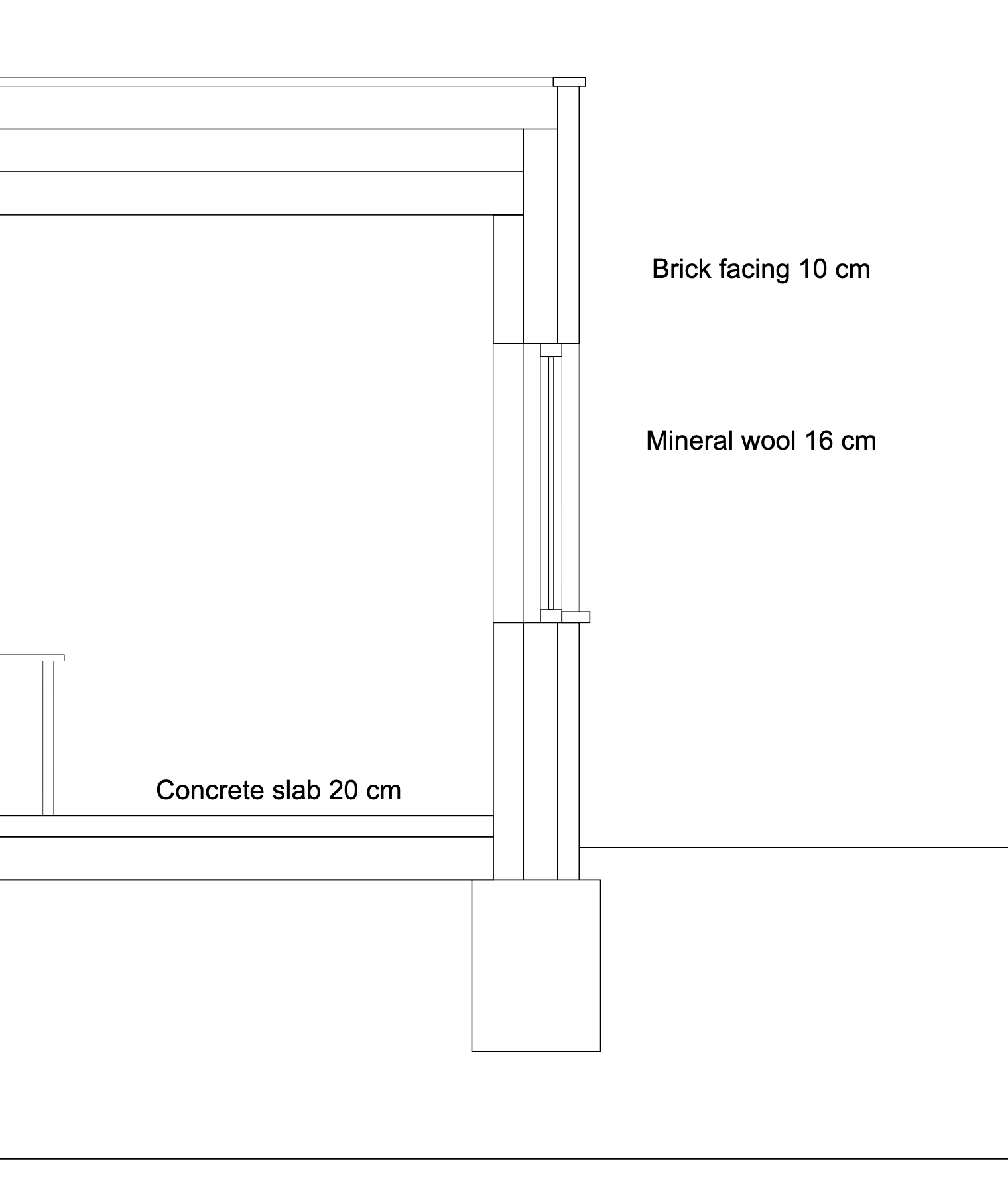
Defaults
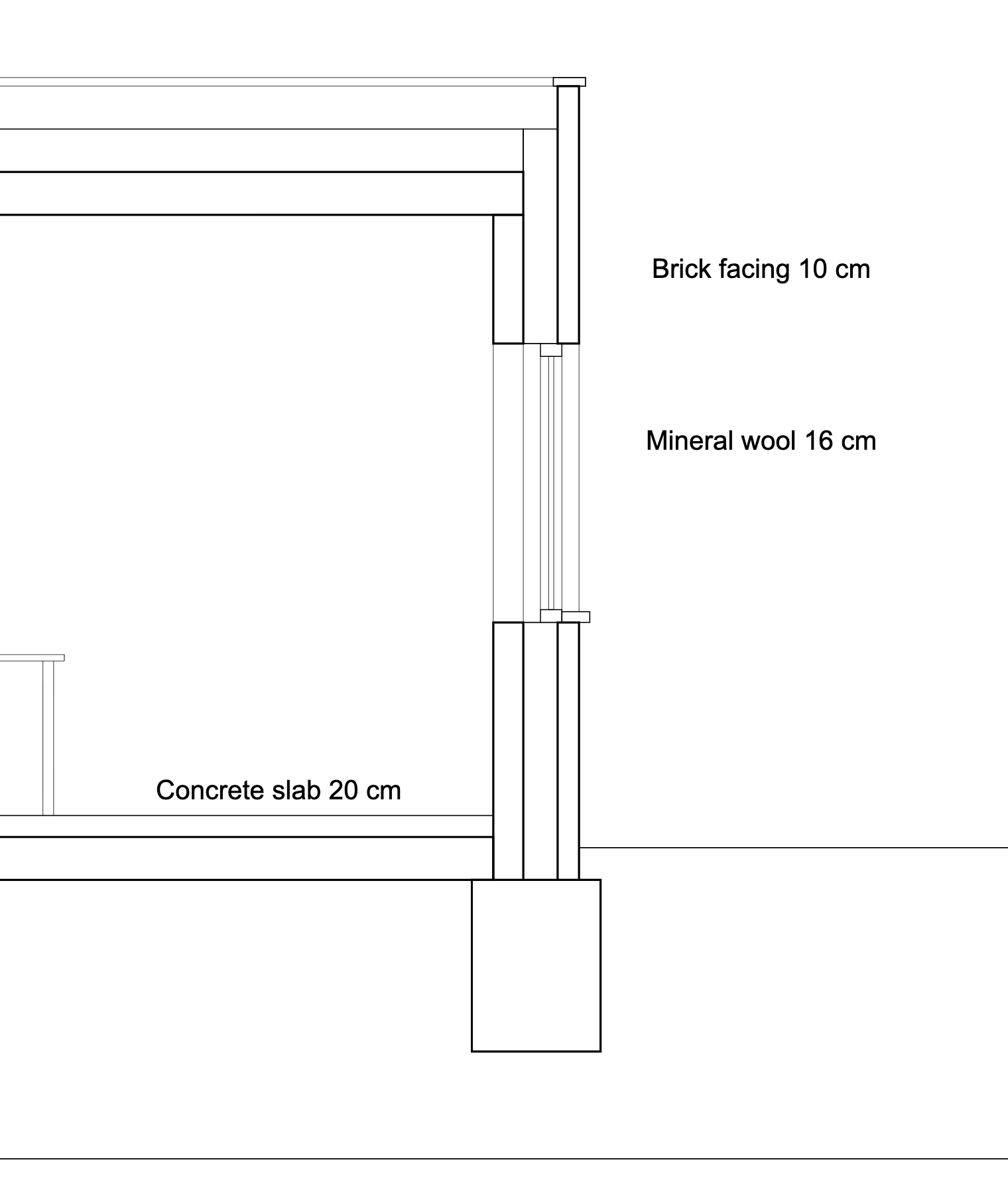
Cut lines BOLD
Line weights
- HAIRLINE
- 0.13 mm — the default of surface lines and hatches.
- THIN
- 0.25 mm — the default of cut lines.
- MEDIUM
- 0.35 mm.
- BOLD
- 0.50 mm.
- HEAVY
- 0.70 mm.
- ULTRA
- 1.00 mm.
In the DXF, each weight is written as AutoCAD's nearest lineweight. With ByLayer ticked, the DXF uses the layer's weight instead of the object's; the SVG and the PDF always draw the object's.
Line types
- NONE
- No line: the object's cut or surface lines are not drawn. Everything else about the object stays — it still hides what is behind it, its fills and symbol are still drawn.
- SOLID
- A continuous line. The default.
- DASHED
- Dashes.
- DOTTED
- Dots.
- DASH-DOT
- Dashes and dots: axes, hidden or demolished elements.
- LONG DASH
- Long dashes.
NONE is the way to keep a cut material's hatch without its outline, or to remove an object's projected lines. With NONE, the rows that style the line are greyed; their values come back with a drawn type.
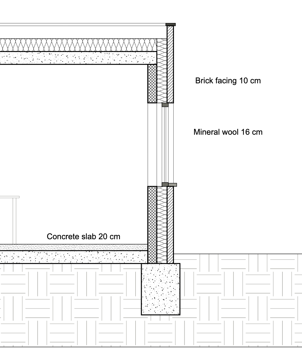
Terrain cut line SOLID
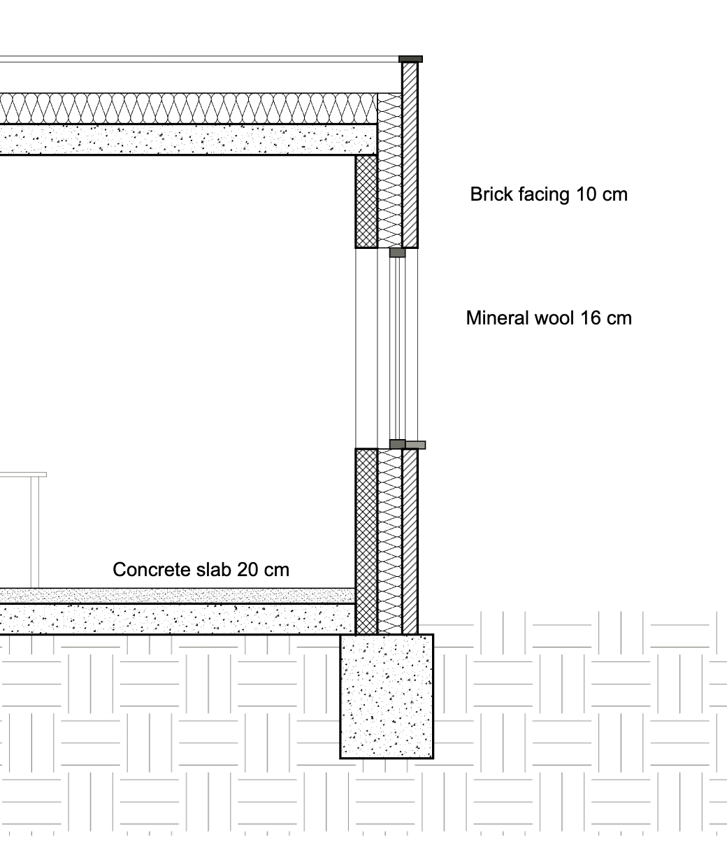
Terrain cut line NONE
Type Scale
Type Scale stretches or tightens the dashes, gaps and dots of the object's line type, from 0.01 to 100: 2 makes them twice as long. Use it when a dashed line reads too busy or too sparse at the drawing's scale. In the DXF it is the entity's linetype scale.
Colour and transparency
Line Color and Transparency (0 % opaque, 100 % invisible) set how the line prints. A grey, or a slight transparency, pushes an object into the background without changing its weight. With ByLayer ticked, the DXF takes the layer's colour; the SVG and PDF keep the object's.
Draw Order
Where two objects overlap in the drawing, Draw Order (under Cut Line Settings) decides which is drawn above: a higher number is drawn later, on top. It applies to every export. Shadows are always drawn above the fills.
A line hierarchy that works
- Main cut elements — structure, walls, slabs: BOLD or HEAVY cut lines.
- Secondary cut elements — linings, insulation, frames: THIN or MEDIUM.
- Projected elements: HAIRLINE, or THIN for what matters most beyond the cut.
- Context — terrain beyond, neighbours, furniture: HAIRLINE in grey, or a dashed type.
- Check the result printed, at the drawing's scale: a hierarchy that reads on screen can merge on paper.
Your own line types and weights
The bottom right tool Line Styles (also in the menu) holds the standard line types and weights, always there, and the project's own. Every Line Type and Line Weight list of the application offers the project's own under Custom.
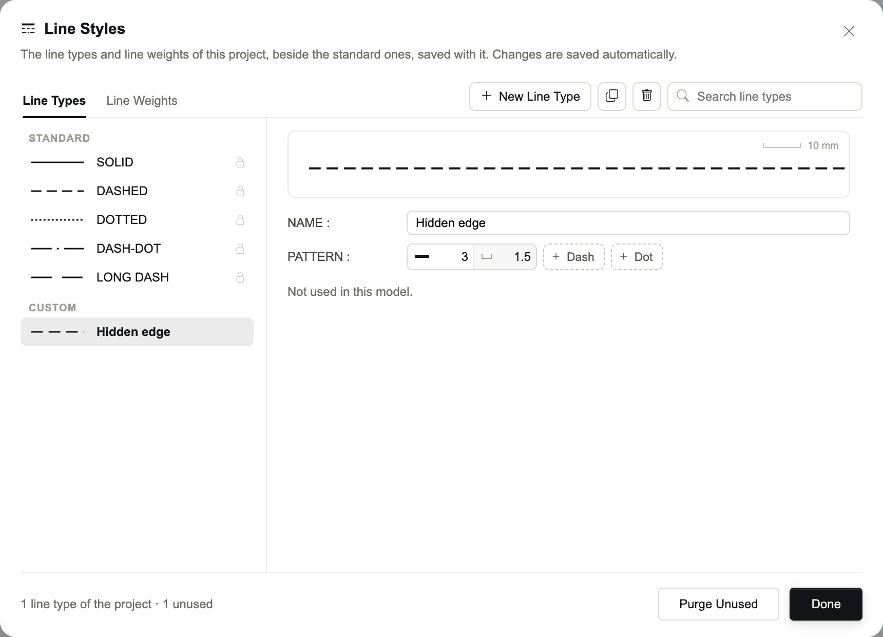
- 01
Make a line type
In Line Types, click New Line Type, then name it. Its pattern is a row of pieces, each a dash or a dot followed by its gap: + Dash and + Dot add a piece, × removes one, up to six pieces.
- 02
Set its lengths
Lengths are millimetres on the printed sheet, from 0.05 to 1000: a 3 mm dash prints 3 mm long whatever the drawing's scale. Type a length and press Enter; ↑ and ↓ change it by 0.5 mm (Shift: 5 mm).
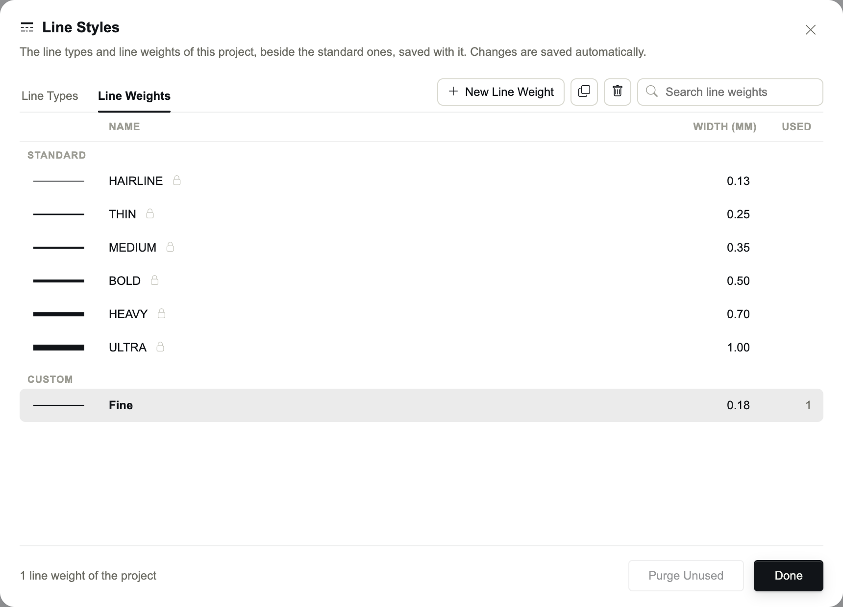
- 03
Or a line weight
In Line Weights, click New Line Weight, name it and set its width, from 0.05 to 2.11 mm.
- Changes apply at once to every line drawn with the style.
- Duplicate starts a new style from the selected one, a standard one included.
- Deleting a style returns what used it to the setting's default. Purge Unused deletes the project's styles nothing in the model uses.
- In the DXF, a custom line type is written under its own name, with its dashes and dots, so it appears in your CAD software as it is.
- A line type's name cannot hold < > / \ " : ; ? * | , = ` ' and cannot be a standard type's name.