Styling
Give every object its graphic style
The object panel decides how an object is drawn: its lines, its fills, its symbol, its layers and its part in shadows. A walkthrough first, then every setting of the panel.
Open an object's settings
In the OBJECTS tab, click the gear at the end of the object's row, or double-click the row. The panel Advanced Object Settings opens with the object's name, and the four buttons of its header:
- Copy
- Copies this object's style, to paste it on others.
- Paste
- Gives this object the copied style. Available once a style is copied.
- Reset
- Returns the object, and what it contains, to the default settings — after asking.
- Back
- Returns to the model browser.
Every change is saved the moment you make it, and can be undone with ⌘Z (Ctrl+Z). Render (⌘↵ or Ctrl+Enter) to see it in the drawing.
Walkthrough: styling a wall section
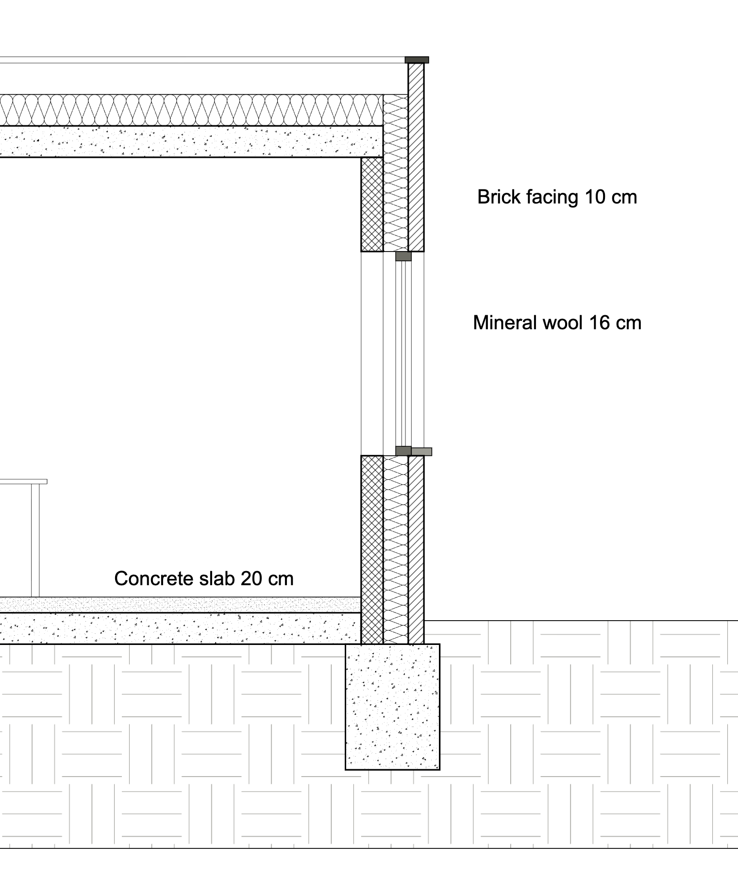
The demo model's Section A-A, from its untouched state to a finished drawing, one decision at a time. Every picture is drawn by Occlusia.
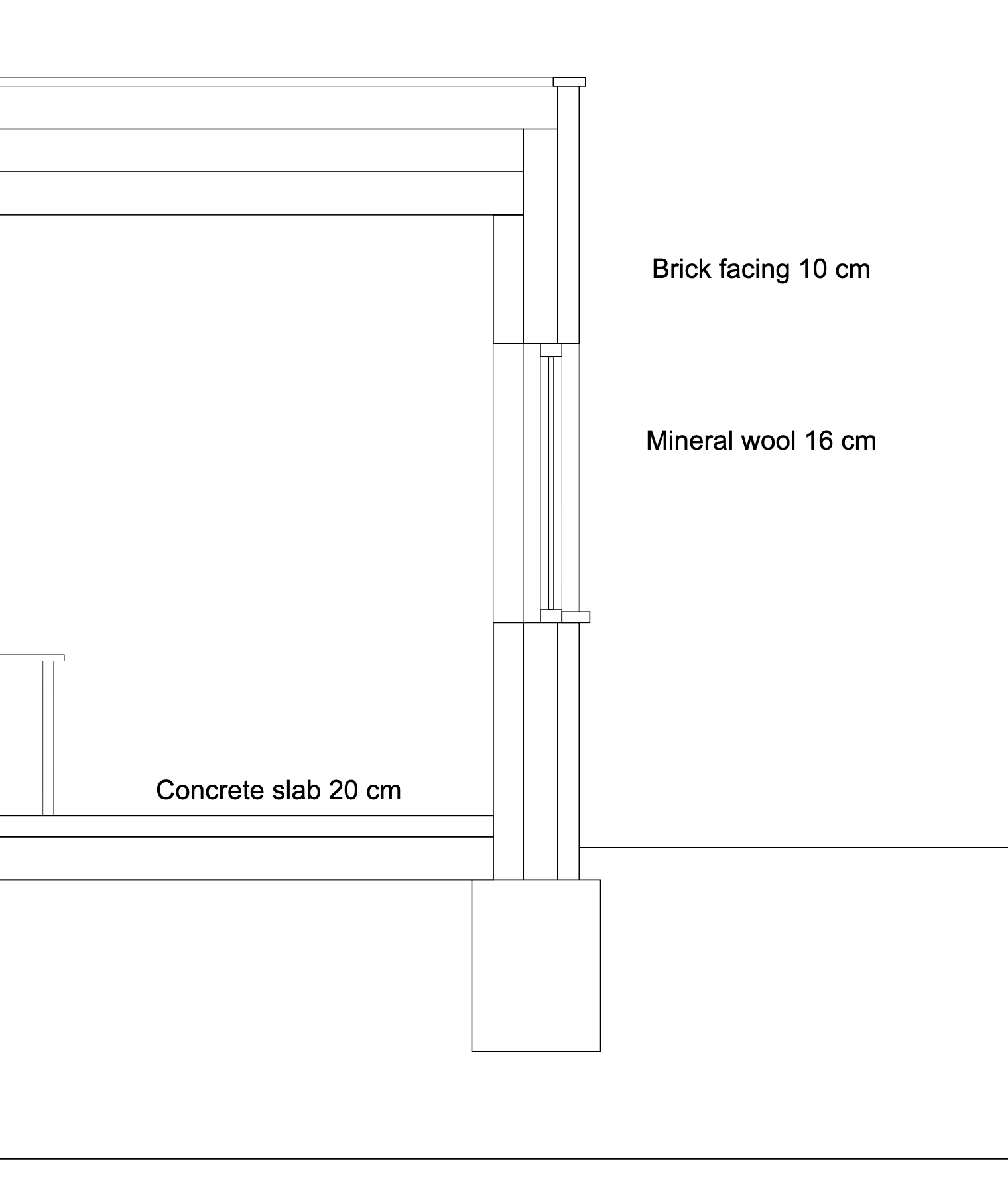
Untouched
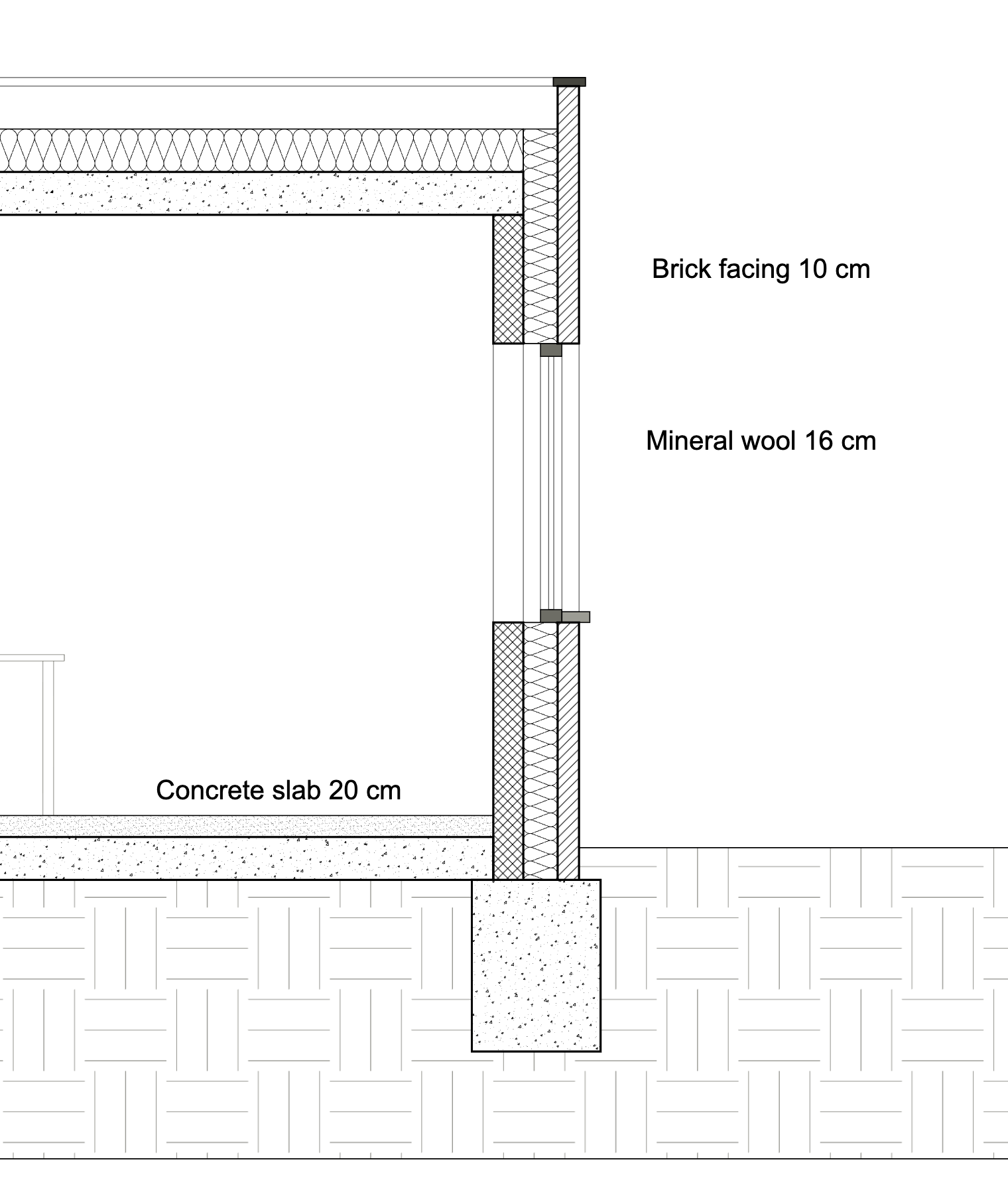
Finished
- 01
Give the cut its weight
Select
Brick,Concrete block,Floor slab,Roof slabandFoundation(⌘-click or Ctrl-click each row), click Edit Selected, and set Cut Line Settings › Line Weight to BOLD. - 02
Fill the cut materials
For each material, open its settings and choose a Fill Type under Cut Pattern Settings: ANSI31 for the brick, ANSI37 for the concrete block, AR-CONC for the concrete, AR-SAND for the screed, EARTH for the terrain. Adjust Scale until the pattern reads well.
- 03
Draw the insulation as insulation
Open
Insulationand set Cut Symbol to INSULATION: the batting curves fill the wall's insulation and the roof's, both namedInsulation. - 04
Finish the details
A SOLID grey fill for the window frame, the sill and the coping, and a grey colour for the terrain's hatch so it stays in the background.
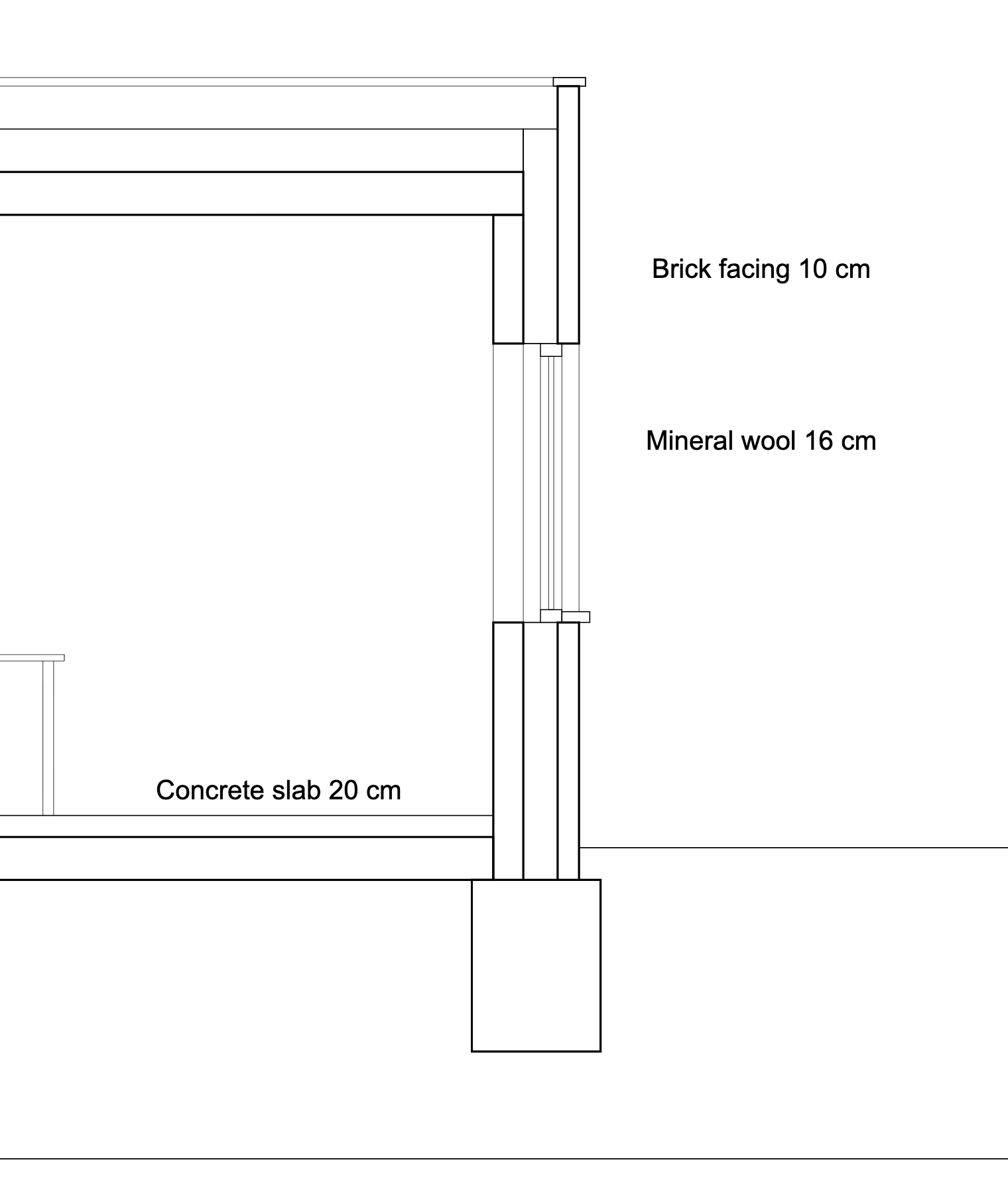
1 · Cut lines
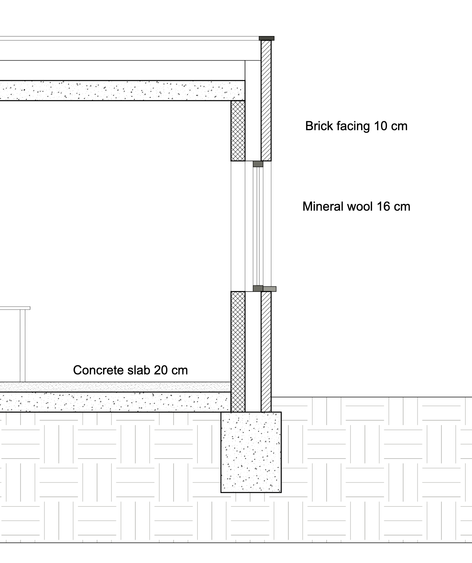
2 · Fills
3 · Symbol
Export as Block
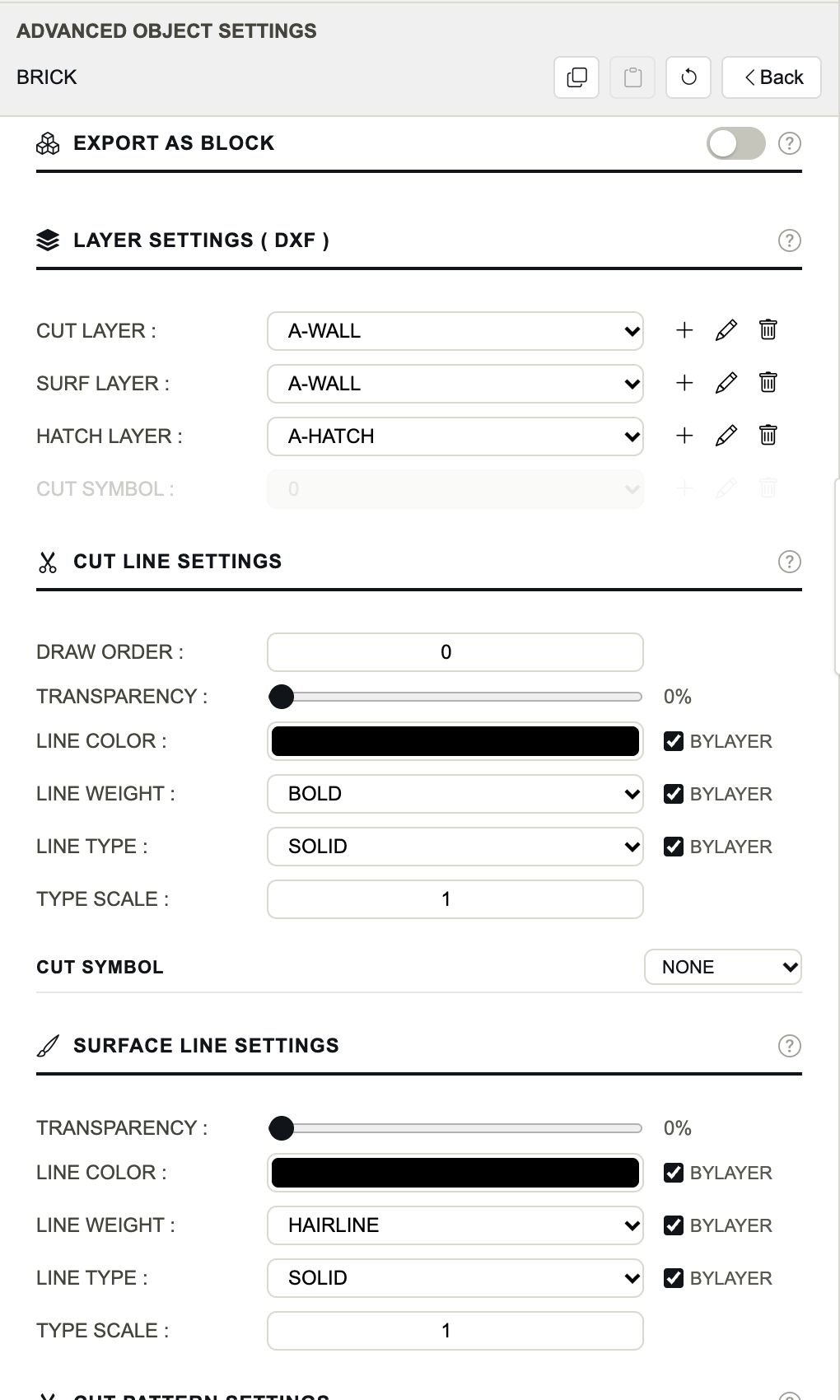
Exports the object and everything inside it as one unit: a block in the DXF, a group in the SVG. A window, a piece of furniture or a detail then moves and selects as one piece in your CAD software. The switch reveals two settings:
- Block Name
- The name of the DXF block and of the SVG group. Empty: the object's own name.
- Block Layer
- The layer of the block reference. What inside it stays on layer 0 takes this layer, as in AutoCAD.
Export as Block belongs to the object alone: unlike every other setting, it does not pass on to the objects inside it, and copy and paste leave it out.
Layer Settings (DXF)
Where the object's parts go in the DXF file. Each row picks a layer of the project; + creates a layer, the pencil edits the selected one, the bin removes it (what used it goes back to layer 0).
- Cut Layer
- The layer of the cut lines.
- Surf Layer
- The layer of the projected lines.
- Hatch Layer
- The layer of the cut and surface hatches. Greyed while the object has no fill.
- Cut Symbol
- The layer of the cut symbol. Greyed while the object has no symbol.
Layers matter in the DXF only; SVG and PDF draw every object with its own colours and weights. See Layers.
Cut Line Settings
The outline of what the view's plane cuts through.
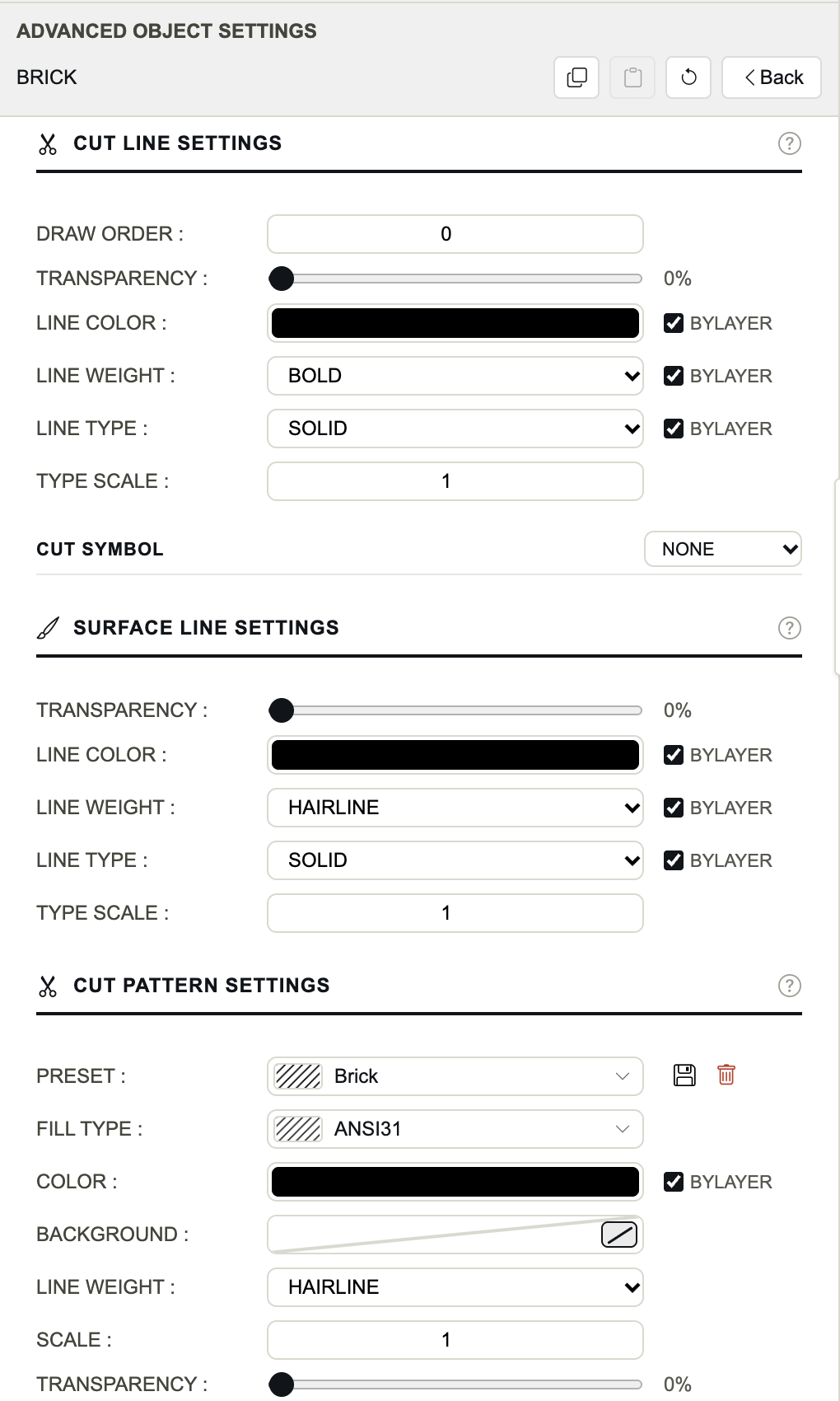
- Draw Order
- Which objects are drawn above others where they overlap: a higher number is drawn later, on top. 0 by default.
- Transparency
- 0 % opaque, 100 % invisible.
- Line Color
- The colour of the cut lines. With ByLayer ticked, the DXF uses the layer's colour instead.
- Line Weight
- HAIRLINE, THIN (default), MEDIUM, BOLD, HEAVY, ULTRA, or one of the project's own. ByLayer: the layer's weight in the DXF.
- Line Type
- NONE, SOLID (default), DASHED, DOTTED, DASH-DOT, LONG DASH, or one of the project's own. NONE draws no cut line at all. ByLayer: the layer's type in the DXF.
- Type Scale
- Stretches or tightens the dashes, gaps and dots of the line type, from 0.01 to 100. 1 by default.
See Lines for the weights, the types and your own line styles.
Cut Symbol
A symbol drawn inside each cut face of the object: INSULATION draws batting, CROSS draws the cross of a structural member. Choosing one reveals the symbol's own lines: Transparency, Line Color, Line Weight and Line Type, each with its ByLayer box. See Cut symbols.
Surface Line Settings
The visible edges of the object beyond the plane — what is seen, not cut. The same settings as the cut lines, without Draw Order: Transparency, Line Color, Line Weight (HAIRLINE by default), Line Type and Type Scale, with their ByLayer boxes. NONE draws no projected line for this object.
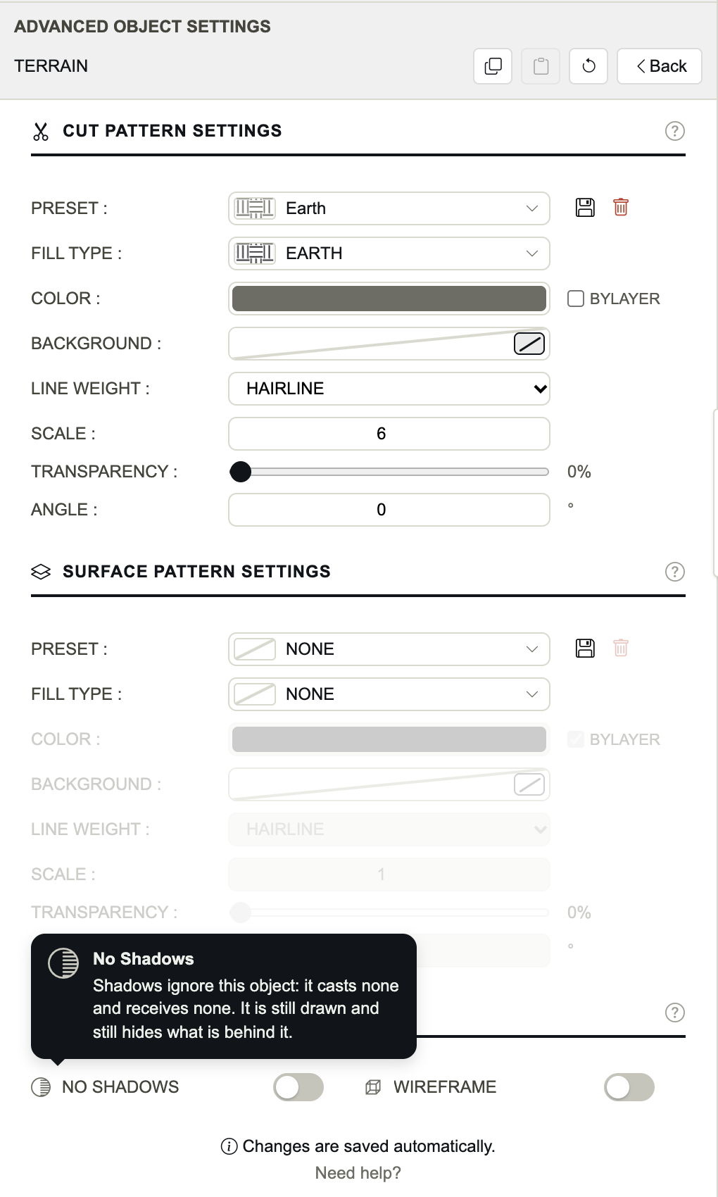
Cut Pattern Settings
The fill of the object where it is cut.
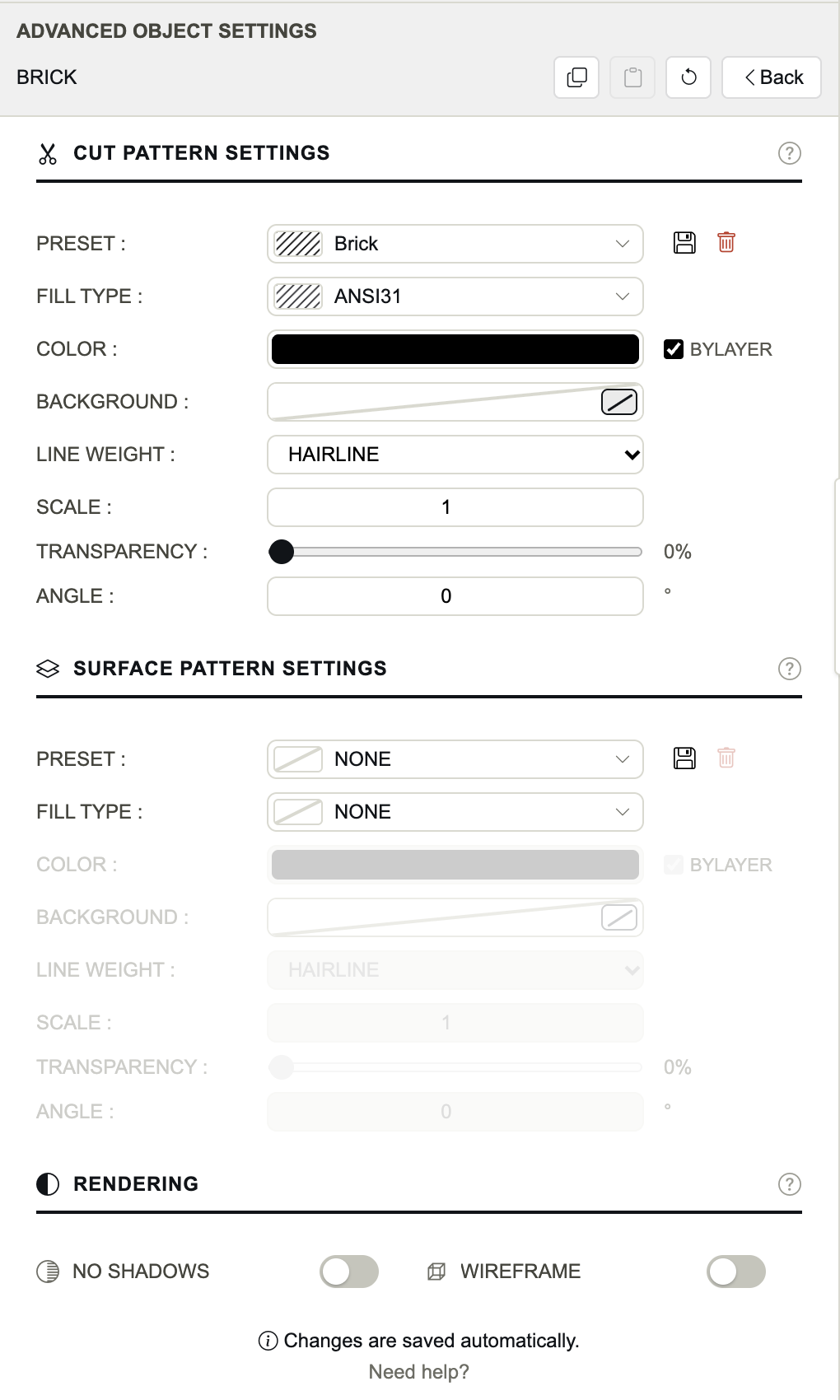
- Preset
- A saved hatch: choosing one sets every row below at once. NONE: no fill. ~ CUSTOM ~: the rows do not match a preset. The floppy saves the rows as a preset, the bin deletes the preset.
- Fill Type
- NONE (default), SOLID, or one of 82 hatch patterns.
- Color
- The colour of the hatch's lines, or of a SOLID fill. ByLayer: the layer's colour in the DXF.
- Background
- A solid colour behind the hatch. The chip in the well turns it off (no background, the default).
- Line Weight
- The weight of the hatch's lines. HAIRLINE by default.
- Scale
- Multiplies the pattern's size: 2 draws it twice as large, 0.5 half as large. From 0.1 to 10.
- Transparency
- 0 % opaque, 100 % invisible.
- Angle
- Turns the pattern, counter-clockwise, in degrees, from −180 to 180.
Rows that do not apply are greyed: with NONE, everything but Preset and Fill Type; with SOLID, Background, Line Weight, Scale and Angle. Their values are kept for when you choose a pattern again. See Fills and hatches.
Surface Pattern Settings
The fill of the object's visible faces beyond the plane: a façade's brick bond in an elevation, a floor's tiling in a plan, a roof's covering. The same settings as the cut pattern, with its own presets. Where a face is partly hidden, only its visible part is filled.
Rendering
- No Shadows
- Shadows ignore the object: it casts none and receives none. It is still drawn and still hides what is behind it.
- Wireframe
- Only the object's lines are drawn: its faces show no fill, hide nothing and cast no shadow. No Shadows then reads on, implied. To keep only an object's cut line, set its surface line type to NONE instead.
Point at an option to read what it does. While Wireframe is on, the object's fills and symbol are greyed: a wireframe has none.
An untouched object
An object nobody styled is drawn with: THIN black solid cut lines, HAIRLINE black solid surface lines, no fill, no symbol, everything on layer 0, all ByLayer boxes ticked, Draw Order 0, casting and receiving shadows. Reset brings an object back to exactly this.
Several objects at once
Select rows with ⌘-click (Ctrl-click) or Shift-click, then click Edit Selected. The panel shows the settings the objects share; a setting where they differ shows — Mixed —. Change it, and every selected object takes the new value — the others stay as they were.
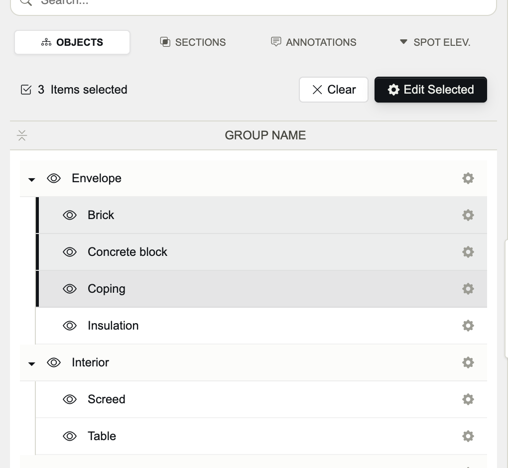
Selection
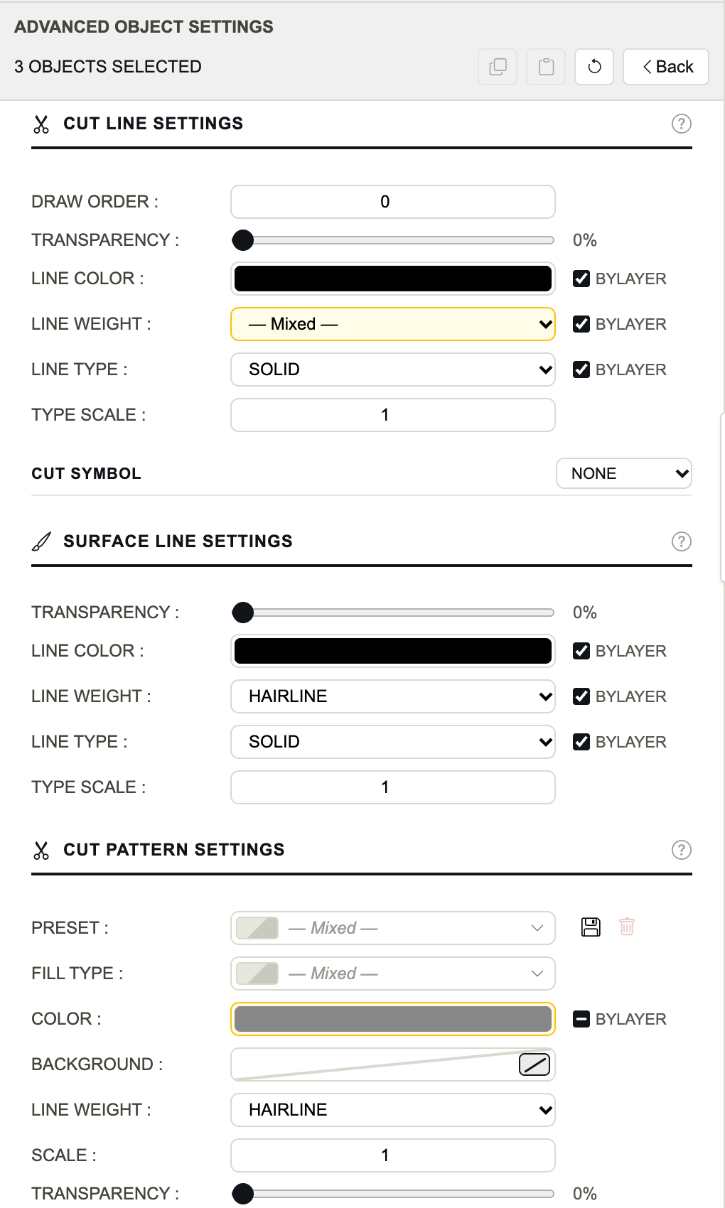
Edit Selected
- Clear empties the selection; Escape too.
- ⌘A (Ctrl+A) selects every row while the pointer is over the tree.
- A preset chosen for a selection is applied to the selected objects only, not to what they contain.
Groups and what they contain
A setting changed on a group is written to the group and to every object inside it, replacing their own value for that setting. Style a whole family from its group, then come back to the one object that must differ. Export as Block is the exception: it never passes on.
Copy, paste and reset
- Copy takes one object's whole style: layers, lines, symbol, both patterns and their presets, Draw Order, No Shadows and Wireframe. Not Export as Block, and not visibility.
- Paste gives that style to the object shown — or to every selected object — and to what they contain. Settings the copied object never set go back to their defaults on the targets.
- The style is read when you paste: change the copied object meanwhile, and the change is pasted too. Opening another project forgets the copy.
- Reset returns the object and what it contains to the defaults, Export as Block included. It asks first, naming how many objects it reaches. Visibility stays as it is.